
The Near-Far Effect: Why Your Radio Works in One Room and Dies in the Next
A first responder keys a portable radio in one room and communicates clearly. Seconds later, another responder moves into an adjacent room: and the transmission becomes weak, intermittent, or unusable.
This is not always a simple “dead zone.” In many buildings, the underlying problem is RF signal imbalance, often associated with the near-far effect.
For building owners, facility managers, and public-safety officials, the consequence is serious: a system may appear to provide adequate downlink coverage during a basic walk test while still failing to deliver dependable uplink talk-back when responders need it most.
What Is the Near-Far Effect?
The near-far effect occurs when a receiver is exposed to a strong signal from a nearby radio while attempting to detect a much weaker signal from a radio farther away.
In a Public Safety Distributed Antenna System (DAS) or Emergency Responder Communication Enhancement System (ERCES), the scenario may look like this:
- A responder keys a portable radio directly beneath or near a service antenna.
- That strong uplink signal reaches the BDA or remote unit at a high power level.
- A second responder transmits from the opposite side of the floor or from a more distant coverage area.
- The weaker “far” signal may be masked, blocked, or lost because the system is responding to the stronger “near” signal.
The result is a communications failure that can be difficult to identify through ordinary testing.
The radio may work. The system may still fail.
A near-far problem is primarily an uplink concern: the path from the responder’s portable radio back through the indoor DAS and toward the public-safety radio network. Downlink signal strength may look acceptable while far-portable talk-back remains unreliable.

Why Signal Imbalance Creates First-Responder Risk
A portable radio located close to a ceiling antenna experiences less path loss than one located at the edge of that antenna’s effective coverage area. The difference can become substantial across a large or heavily partitioned floor plate.
When a strong uplink enters the system, the BDA’s automatic gain control or automatic level control: AGC/ALC: may reduce amplification to prevent overload, instability, or distortion. Depending on the equipment architecture and configuration, that gain reduction can make weaker transmissions harder for the system to receive.
This can produce several symptoms:
- A responder can hear others but cannot be heard clearly.
- A transmission drops when the user moves between rooms.
- Radio performance changes when another radio is keyed nearby.
- Coverage appears strong during a single-user test but deteriorates during simultaneous transmissions.
- The BDA reports stable operation, yet the far radio experiences “out of range” conditions.
- A system passes a basic signal-strength check but fails a more realistic communications test.
These conditions are especially concerning in stairwells, parking structures, mechanical rooms, hospitals, high-rise buildings, and other locations where building materials and architectural obstructions increase propagation loss.
RF Design Issues That Contribute to the Problem
1. Insufficient Antenna Density
A single service antenna cannot provide uniform RF performance across every room, corridor, stairwell, and obstruction-filled space.
When antennas are spaced too far apart, the signal level near one antenna may be dramatically stronger than the signal at the edge of coverage. Increasing antenna density reduces the distance a portable radio must transmit to reach an effective service antenna.
A professional design should evaluate:
- Floor-plan geometry and building materials
- Concrete, steel, fire-rated walls, and low-emissivity glass
- Stairwells, elevator lobbies, basements, and parking areas
- Antenna spacing and cable-loss budgets
- Required coverage zones under the applicable local fire code
- Uplink performance: not only downlink signal strength
A more uniform RF environment helps reduce the power difference between near and far portables.
2. Improper Gain and Link-Budget Calculations
BDA gain should not simply be set to the highest available value. Excessive gain can create instability, overload, oscillation, or unwanted noise. Insufficient gain can leave distant areas below the required operating threshold.
A complete link budget considers:
- Donor signal level
- Donor coaxial loss
- BDA gain
- Splitter and coupler loss
- Feeder cable loss
- Antenna gain
- Building penetration loss
- Uplink and downlink requirements
- Receiver sensitivity and dynamic range
The objective is balanced, controlled amplification. The strongest path should not overwhelm the system, and the weakest required path should not be neglected.
3. BDA Architecture and AGC Behavior
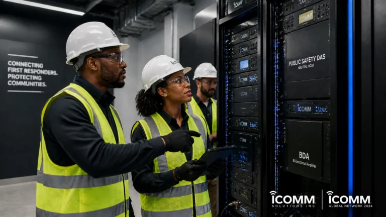
BDA classification and channel architecture also matter. A Class A channelized BDA can provide independent filtering and gain control for individual channels, which may improve control of unwanted signals and channel-specific overload conditions.
Broadband or Class B equipment may respond differently depending on the system design, public-safety frequencies, and manufacturer configuration. The important point is not to select equipment based solely on headline output power. The BDA must be engineered for the jurisdiction’s radio channels, donor conditions, coverage objectives, and operating environment.
The correct design question
Do not ask only, “How much signal can the BDA produce?”
Ask instead:
Can the system maintain intelligible, reliable communications when strong and weak portables operate at the same time?
4. Inadequate RF Isolation
Isolation is the separation between antennas or system paths that prevents unwanted feedback and re-entry.
Two isolation concerns are especially important:
- Donor-to-coverage isolation: separation between the outdoor donor antenna and the indoor coverage network
- Antenna-to-antenna isolation: separation between indoor service antennas and other RF sources within the distribution system
Poor isolation can cause feedback, oscillation, system alarms, gain reduction, or desensitization. It may also force the BDA to operate conservatively, reducing usable performance across the building.
Isolation targets must be calculated and verified according to the selected equipment, system gain, design, and Authority Having Jurisdiction (AHJ) requirements. Common engineering guidance references margins above system gain, but the final acceptance criteria are jurisdiction-specific.

How Professional ERCES Design Addresses Near-Far Conditions
A reliable Public Safety DAS/ERCES begins before installation. It starts with a documented RF design process.
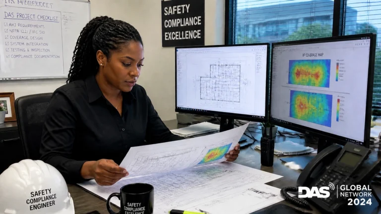
RF modeling and predictive design
Predictive modeling helps engineers visualize expected signal behavior before cable is installed or walls are closed. The model should account for building attenuation, antenna placement, cable paths, splitters, couplers, and equipment performance.
Modeling can identify:
- Large variations in signal level across one floor
- Areas where antenna spacing is too wide
- High-loss construction zones
- Potential coverage gaps in stairwells and below-grade areas
- Locations requiring additional service antennas
- Excessive feeder loss or poorly balanced distribution paths
Modeling is not a substitute for field verification. It is a planning tool that improves the probability of a first-pass installation and helps control costly changes during construction.
Controlled antenna placement
Antennas should be positioned to create predictable, overlapping coverage: not simply placed wherever cable routing is convenient.
The design must consider the relationship between:
- Antenna height
- Floor layout
- Expected portable-radio location
- Required coverage threshold
- Uplink margin
- Adjacent antenna overlap
- Fire-rated and restricted-access areas
The goal is a uniform RF footprint that minimizes extreme differences between near and far users.
Filtering and donor optimization
Strong external signals, intermodulation products, or unwanted RF energy can affect the BDA’s operating range. Proper donor antenna selection, filtering, grounding, and system configuration help protect the public-safety band from interference.
A qualified designer should evaluate the external RF environment instead of assuming that an available donor signal is automatically suitable.
Commissioning and Testing: Where Design Becomes Proof
A system is not complete when the BDA powers on. It is complete when documented testing demonstrates that the system performs under realistic operating conditions.
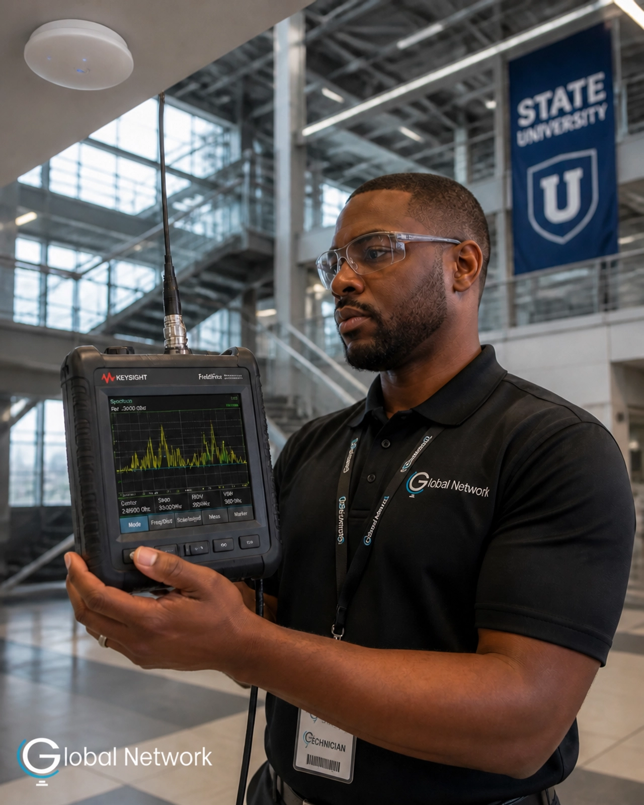
Commissioning should include, as applicable:
- Donor signal verification
- Downlink and uplink signal measurements
- Cable and component loss verification
- BDA gain and attenuation settings
- Oscillation and stability checks
- Antenna-to-antenna isolation testing
- Donor-to-coverage isolation testing
- Battery and power-supply verification
- Alarm and supervisory monitoring
- DAQ or intelligibility testing
- Code-required grid testing
- Near-far or simultaneous-transmission testing
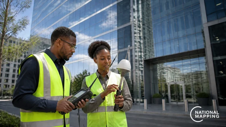
Testing the near-far condition
A practical near-far evaluation uses two comparable portable radios:
- One radio transmits close to a service antenna.
- The second radio transmits from a far-side or edge-of-coverage location.
- Technicians observe whether the far radio remains intelligible and connected while the near radio is active.
- The process is repeated in representative areas, including difficult coverage zones.
This test is more meaningful than checking signal strength with one radio at a time. It evaluates whether the system can preserve communications when the RF environment becomes demanding.

Compliance Is More Than a Checklist
Local requirements may incorporate provisions from IFC 510, NFPA 72, and NFPA 1225, along with amendments and testing procedures adopted by the Authority Having Jurisdiction.
The exact requirements vary by location and project type. However, the operational objective remains consistent:
First responders must be able to communicate where and when it matters most.
A code-compliant design should be supported by:
- Engineered drawings
- Equipment documentation
- Permit coordination
- Installation records
- Acceptance-test results
- As-built documentation
- Inspection support
- Annual performance testing where required
A passing result should reflect dependable performance: not a temporary adjustment made only for inspection day.
The Global Network LLC Approach
Global Network LLC provides Public Safety DAS/ERCES design, BDA installation, compliance testing, commissioning, and annual performance support for facilities throughout Atlanta and surrounding markets.
Your project receives a code-focused evaluation of:
- RF coverage and uplink reliability
- Near-far exposure
- Antenna density
- Isolation margins
- BDA configuration
- Building-specific propagation loss
- IFC and NFPA documentation requirements
- FirstNet-compatible design considerations where applicable
0% Guesswork. 0% Missed Deadlines. A safer path to compliance.
Whether the project involves a new construction, occupancy delay, renovation, fire-marshal correction, or scheduled annual test, professional RF engineering protects both the building and the people who depend on it.
Identify the Imbalance Before It Becomes an Emergency
If a radio works in one room and fails in the next, do not assume the problem is limited to a weak signal. It may involve near-far behavior, uplink imbalance, insufficient antenna density, inadequate isolation, or improper BDA gain control.
Request a professional evaluation before the issue becomes an inspection failure or an emergency communications gap.
Contact Global Network LLC at 770.520.7633 or 877.231.1084. Learn more about our DAS and ERCES services, review our Public Safety DAS/ERCES resources, or visit globalnetworkco.com.
For additional background, consult the Safer Buildings public-safety primer, the FCC overview of public-safety propagation, and relevant guidance from your local AHJ.